°°
Download and read HELP
and User manual file for ELFEN

1.
µ„ª˜œ¬‘ÿŒƒº˛(password:
uutx)£¨À´ª˜¥Úø™Œƒº˛(.exe)£ª
2. ªÒµ√∏ˆ»ÀµÁƒ‘ª˙∆˜¬Î£®»Áœ¬Õº£©£ª
3. Ω´ª˙∆˜¬Î∑¢ÀÕ” º˛µΩwangyl@tsinghua.org.cn£¨ªÒµ√Œƒº˛‘ƒ∂¡∫Õ π”√√Ьΰ£
°°
°°
Parallel computation
of ELFEN
°°
°°
Summary
of ELFEN Key Features for the User Interface
°°
General Features
-
Versatile screen layout
with user-friendly Graphical User Interface (GUI).
-
Use of icons, selection
lists, buttons and sliders to control programs.
-
Easy to use view facility.
-
Single view of 2D, or
rotated 3D objects.
-
Four view layout available,
also showing elevations in X, Y or Z directions.
-
Dynamic rotation of
geometry on screen in full 3D using the mouse.
-
Rotation angle selectable
via slider or value, X, Y or Z elevations instantly selectable.
-
Reverse instantly
selectable to view other side of object.
-
Full interactive zoom and
resize facility.
-
Selection using lists or
graphical display, single and multiple items or selection.
-
Save and recall selected
views.
-
Component rotation from
camera or object viewpoint.
-
View may be either
Orthographic or Perspective.
-
On screen cursor speed
control.
-
Hard copy.
Pre-Processor
-
Parametric geometry
definition using tokens.
-
Point, line, arc, circle,
and quadratic curves.
-
Geometry can be generated
graphically or imported from a CAD system (including NURBS surfaces and
tessellated surfaces).
-
CAD-style facilities such
as copy, move, rotate and mirror.
-
Angular units can be
degrees or radians.
-
Automatic surface and
volume generation from wireframe.
-
Automatic generation of
particulate geometry (2D disks and 3D spheres).
-
Automatic generation of
pre-existing fractures (joint sets).
-
On-screen labelling of
geometry entities.
-
Visibility toggling for
geometric entities
-
ELFEN gem file format - may
be used to import data from other systems.
-
Collections of geometric
entities can be defined as objects for slideline contact, adaptivity and
multi-stage analyses.
-
Local co-ordinate systems
for beams and structural fixities.
Loading
-
Point loading.
-
Pressure/face loading with
distribution defined across the domain.
-
Body forces and gravity.
-
Applied displacements,
velocities, accelerations and temperatures.
-
Thermal loading for both
transient and steady-state problems.
-
Fluid loads, e.g. pressure
and velocity.
-
Seepage loads, e.g.
prescribed pore pressure.
-
Initial stress and strain
fields.
-
Point masses.
-
Multiple load cases.
-
Load functions for
nonlinear and dynamic analyses, with facilities for importing and
manipulating load curves.
-
Load relaxation for gradual
deactivation of load
Initial Conditions
-
Initial and reference
temperatures.
-
Geostatic initialisation
for geotechnical projects.
-
Initial porosity, pore
pressure, liquid saturation and gas saturation..
Constraints and Boundary Conditions
-
Structural fixities and
coupled constraints.
-
Initial and reference
temperatures.
-
Infinite and non-reflecting
boundaries.
-
Damping for dynamic
analysis.
-
Constraint relaxation for
gradual release of structural fixities.
Contact
-
Slideline contact with
friction.
-
Deformable/rigid surfaces.
-
Discrete element contact
(including fracture for appropriate material models).
Materials Database
-
Interactive materials
database.
-
Wide range of material
models.
-
Wide range of failure and
damage models.
-
Several separate databases
may be defined.
-
Direct link with
pre-processor.
-
Hard copy facility.
-
Graph facility.
-
Access can be controlled
via password.
-
Alternative format
.use material property files,
e.g. for seepage analysis.
Mesh Generation
-
Structured mesh generation
2D or 3D, with triangular, quadrilateral, hexahedral and tetrahedral
elements of 3, 4, 8, 9, and 20 nodes.
-
Structured mesh
specification by equal, weighted or progressive divisions, with default.
-
Unstructured mesh
generation 2D or 3D, with triangular, quadrilateral or tetrahedral elements
with 3, 6, 4 and 10 nodes.
-
Unstructured mesh sizes
applied to volume, surface, line/arc or point entities, in a hierarchical
structure.
-
Delaunay and Advancing
Front algorithms for unstructured meshing.
-
Density regions for initial
mesh for unstructured meshing (independent of geometric items).
-
Adaptive remeshing on
unstructured meshes in 2D and 3D, including mesh regions for localised mesh
density control.
-
Range of error computation
algorithms for controlling adaptive remeshing.
-
Mesh refinement.
Analysis
-
Single or multi-field
analyses, using both Implicit and Explicit solution methods.
-
Field types include:
Mechanical - including linear elastic, nonlinear (material and geometric
nonlinearity), dynamic relaxation, discrete and combined finite/discrete.
Thermal (and general quasi-harmonic field problems)
Fluid
Seepage
-
Internal and external
coupling schemes for multi-field projects.
-
Range of Implicit solvers,
with both incremental and arc-length schemes.
-
Output control, e.g., data
echo, individual variable values, nodal values, integration point values.
-
Element options, e.g.
integration rules, use of special strain interpolation algorithms.
-
Equation solution
optimisers.
-
High resolution history
graph plot definition.
-
Material grid definition.
-
Output filtering.
-
Multi-stage definition.
-
Adaptivity definition with
specification of local regions of mesh refinement.
-
Mass scaling for explicit
timestep control.
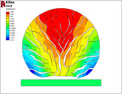
Visualisation
-
New module for results
processing.
-
Uses binary output file for
reduced size and increased efficiency.
-
Ability to load multiple
result sets simultaneously.
-
Time selection by slider
with real-time screen update, or selection of specific output from stack.
-
Mouse controlled zoom, pan
and rotate of display in real time.
-
Shaded images with flexible
lighting options, brightness and colour control.
-
Layer selection for layered
shells and beams.
-
Domain items selected from
list, with visibility toggling.
-
Mesh plotting styles: Wire
frame, Solid, Profile, Edgeless.
-
Contour plots: Automatic or
user defined contour bands, User-specified contour key style, Texture
mapping
-
Display tools: Sectioning,
Isosurfaces for contour plots, MRI, Reference grid display, Axis display,
ìMouse-over� information for on-screen description of nearest entity.
-
Vector plots:
User-specified contour key style, Choice of line style, Scaling of vector
size.
-
Graph plotting: Multiple
nodes and/or time increments, Graphs along arbitrary section lines, Export
of graph data in tabular form, High resolution history graph plotting.
-
Geometric manipulation
facilities, e.g. mirror, copy.
-
Result combinations.
-
Animations in AVI format.